


COUPLER
Lossless looping
of video data
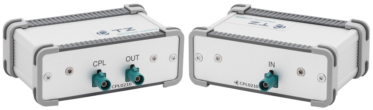
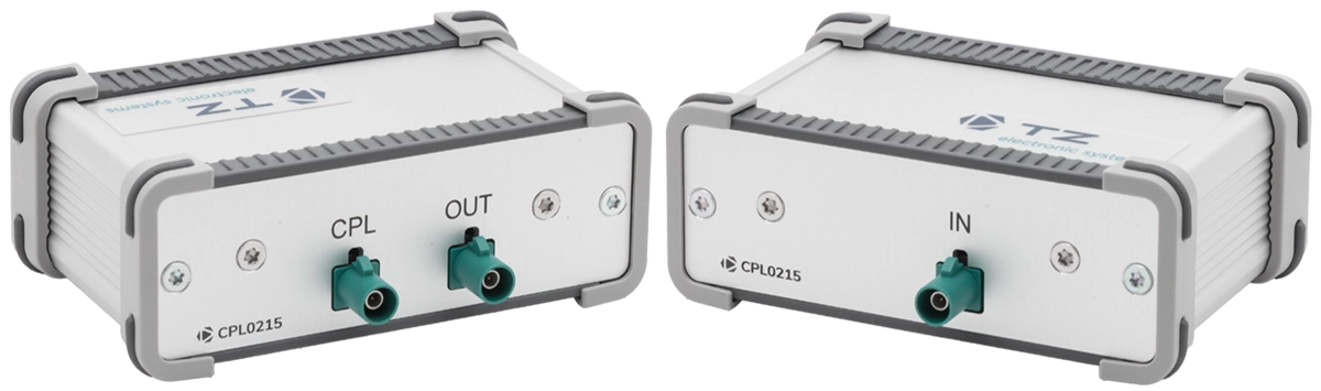
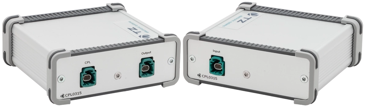
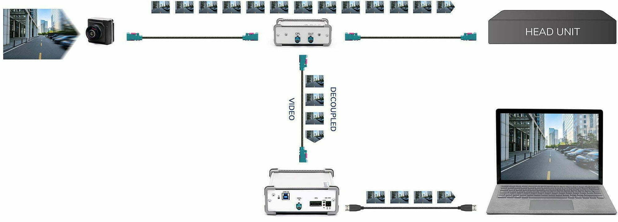
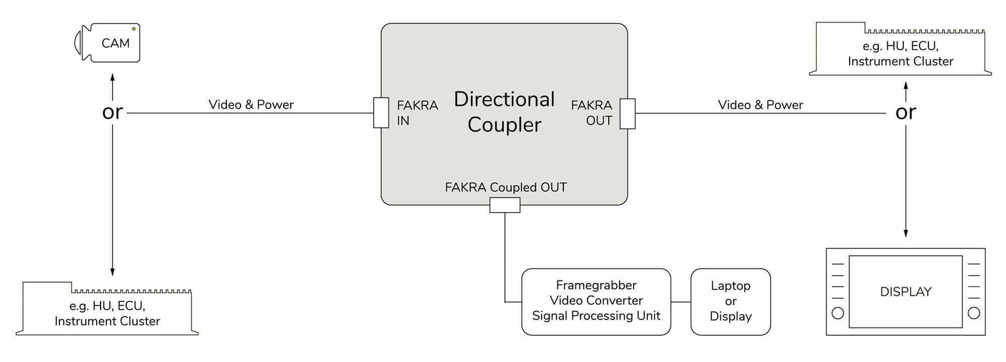
Our Couplers were developed to loop out video signals of automotive video systems in real operation for analysis and recording. Their particular advantage lies in their passive mode of operation: This makes them independent of the installed technology, and reduces the impacts on connected components such as a camera, head unit or display to an absolute minimum, thereby guaranteeing signal integity.
A signal sniffer can also be connected if the control channel data needs to be decoupled.
TZ Couplers are series-produced for the generally used GMSL and FPD-LINK technology standards. We will be pleased to realize other technologies and connectors individually for you on request.
scroll
Applications
- Monitoring and recording of video signals during real operation
- Recording of decoupled video signals during test and trial runs
- Hardware-in-the-loop tests (long-term tests)
Functions
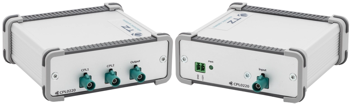
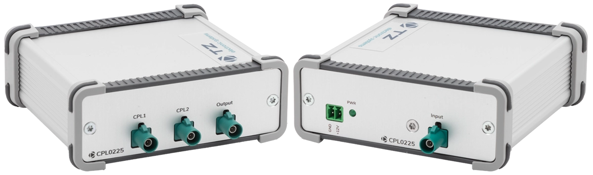
Our Couplers allow the simple and accurate decoupling of video signals – purely passive or partially active devices are available, depending on the task.
Purely Passive or Partially Active Function
Our purely passive Couplers are the prime choice for shorter cable lengths in the looped-out path. Partially active variants in which the looped-out signal is amplified and additionally duplicated are available for test setups where longer cables are required.
Product Overview
Scope of Supply
All our test devices are supplied ready for use including all components necessary for operation, such as power supply, cables and plugs, etc.